
AWS 3-Tier Architecture Diagram: A Complete Guide to Production-Ready Web Applications
The three-tier architecture is the most widely adopted pattern for production web applications on AWS. It separates an application into three logical layers, presentation, application, and data, to enable independent scalability, enhanced security, and maintainability. This separation of concerns improves security, scalability, and maintainability by isolating each component.
A three-tier architecture is suitable for building a wide range of applications such as web applications, enterprise systems, and mobile apps. It provides a general framework to ensure decoupled and independently scalable application components can be separately developed, managed, and maintained (often by distinct teams).
This guide provides a complete reference for the AWS 3-tier architecture, what it is, how it works, and how to deploy it following AWS best practices.
Cloud Architecture
Create cloud architecture diagrams for AWS, Azure, GCP, and more. Design scalable infrastructure with professional cloud icons.
Complete guide to the AWS 3-tier architecture diagram, presentation, application, and database tiers with Multi-AZ, Auto Scaling, and security best practices.
Click Cloud Architecture to open AI Line Studio and generate diagrams from natural language in seconds.
What Is a 3-Tier Architecture?
A 3-tier architecture divides a web application into three layers:
- Presentation Tier (Web Layer): The user-facing frontend. This is where the application's endpoint lives and where a user is presented with information. Handles the user interface and client requests.
- Application Tier (Logic Layer): The backend that processes business logic, executes API requests, and orchestrates data flow between the presentation and data tiers.
- Database Tier (Data Layer): The storage layer that persists application data using databases, caches, or file systems.
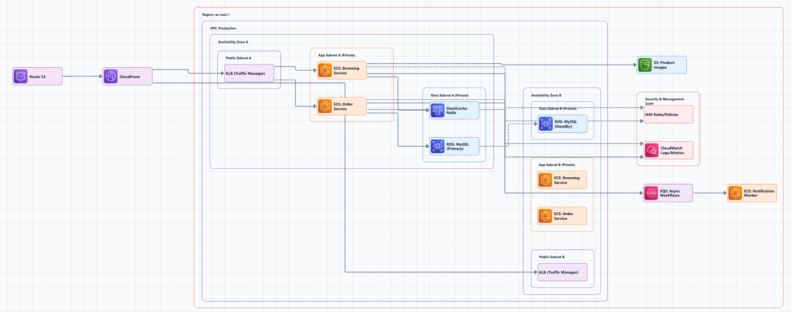
This separation contrasts with monolithic architectures where the frontend, backend, and database all reside in the same place. The multi-tier pattern provides a general framework for decoupled and independently scalable components.
The Three Tiers: Detailed Breakdown
Tier 1: Presentation Tier (Web Layer)
Purpose: Serves the user interface and handles incoming client requests.
Key Components:
- Amazon CloudFront: Global content delivery network (CDN) that caches static assets at edge locations for low-latency delivery.
- AWS WAF: Web Application Firewall that protects against common web exploits and attacks.
- Application Load Balancer (ALB): An internet-facing load balancer that distributes incoming traffic across web servers in public subnets.
- Amazon Route 53: Scalable DNS and traffic management service that routes end-user requests.
Network Placement: The presentation tier typically resides in public subnets within the VPC. The ALB sits in the public subnet and acts as the entry point for all internet traffic.
Auto Scaling: Web servers are placed in an Auto Scaling Group to automatically adjust capacity based on demand.
Tier 2: Application Tier (Logic Layer)
Purpose: Executes business logic, processes API requests, and coordinates application functionality.
Key Components:
- EC2 Instances or ECS/EKS Containers: Run the application code (Node.js, Python, Java, .NET, etc.).
- Internal Application Load Balancer (ALB): A private load balancer that routes traffic from the web tier to the application tier.
- Auto Scaling Group: Dynamically scales application instances based on CPU utilization or custom metrics.
- Amazon ElastiCache: In-memory caching (Redis or Memcached) to reduce database load and improve performance.
Network Placement: The application tier is deployed in private subnets, accessible only from within the VPC. This ensures backend logic is never exposed directly to the internet.
Egress: NAT Gateways in the public subnets allow application instances in private subnets to access the internet for updates and patches without exposing them to inbound traffic.
Tier 3: Database Tier (Data Layer)
Purpose: Stores and manages application data with high durability and availability.
Key Components:
- Amazon RDS: Managed relational database service (MySQL, PostgreSQL, Aurora, etc.) with automated backups, patching, and replication.
- Multi-AZ Deployment: Synchronous replication from a primary database instance to a standby instance in a different Availability Zone.
- Amazon DynamoDB: NoSQL database option for applications requiring single-digit millisecond latency and automatic scaling.
- Amazon S3: Object storage for backups, static assets, and data lake storage.
Network Placement: The database tier resides in isolated subnets and is only accessible from the application tier.
High Availability: Multi-AZ configuration provides automatic failover. If the primary database fails, AWS automatically promotes the standby replica.
Complete 3-Tier Architecture Diagram
Diagram Structure (Left to Right, Top to Bottom)
┌─────────────────────────────────────────────────────────────────────────────┐
│                           AWS Cloud                                        │
│  ┌───────────────────────────────────────────────────────────────────────┐ │
│  │                        Region (e.g., us-east-1)                       │ │
│  │                                                                       │ │
│  │  ┌─────────────────────────────────────────────────────────────────┐ │ │
│  │  │                         VPC (10.0.0.0/16)                       │ │ │
│  │  │                                                                 │ │ │
│  │  │  ┌───────────────────────────────────────────────────────────┐  │ │ │
│  │  │  │                    Availability Zone 1                    │  │ │ │
│  │  │  │  ┌─────────────────────┐  ┌─────────────────────────────┐ │  │ │ │
│  │  │  │  │   Public Subnet 1   │  │     Private Subnet 1         │ │  │ │ │
│  │  │  │  │   (10.0.1.0/24)     │  │     (10.0.10.0/24)           │ │  │ │ │
│  │  │  │  │                     │  │                              │ │  │ │ │
│  │  │  │  │  ┌───────────────┐  │  │  ┌────────────────────────┐  │ │  │ │ │
│  │  │  │  │  │  NAT Gateway  │  │  │  │  Web Servers (EC2)     │  │ │  │ │ │
│  │  │  │  │  └───────────────┘  │  │  │  (Auto Scaling Group)  │  │ │  │ │ │
│  │  │  │  │                     │  │  └────────────────────────┘  │ │  │ │ │
│  │  │  │  │  ┌───────────────┐  │  │                              │ │  │ │ │
│  │  │  │  │  │  ALB (Public) │  │  │  ┌────────────────────────┐  │ │  │ │ │
│  │  │  │  │  └───────────────┘  │  │  │  App Servers (EC2)     │  │ │  │ │ │
│  │  │  │  │                     │  │  │  (Auto Scaling Group)  │  │ │  │ │ │
│  │  │  │  └─────────────────────┘  │  └────────────────────────┘  │ │  │ │ │
│  │  │  │                           │                              │ │  │ │ │
│  │  │  │                           │  ┌────────────────────────┐  │ │  │ │ │
│  │  │  │                           │  │  RDS (Primary)         │  │ │  │ │ │
│  │  │  │                           │  │  (Multi-AZ)            │  │ │  │ │ │
│  │  │  │                           │  └────────────────────────┘  │ │  │ │ │
│  │  │  │                           └─────────────────────────────┘ │  │ │ │
│  │  │  └───────────────────────────────────────────────────────────┘  │ │ │
│  │  │                                                                 │ │ │
│  │  │  ┌───────────────────────────────────────────────────────────┐  │ │ │
│  │  │  │                    Availability Zone 2                    │  │ │ │
│  │  │  │  ┌─────────────────────┐  ┌─────────────────────────────┐ │  │ │ │
│  │  │  │  │   Public Subnet 2   │  │     Private Subnet 2         │ │  │ │ │
│  │  │  │  │   (10.0.2.0/24)     │  │     (10.0.11.0/24)           │ │  │ │ │
│  │  │  │  │                     │  │                              │ │  │ │ │
│  │  │  │  │  ┌───────────────┐  │  │  ┌────────────────────────┐  │ │  │ │ │
│  │  │  │  │  │  NAT Gateway  │  │  │  │  Web Servers (EC2)     │  │ │  │ │ │
│  │  │  │  │  └───────────────┘  │  │  │  (Auto Scaling Group)  │  │ │  │ │ │
│  │  │  │  └─────────────────────┘  │  └────────────────────────┘  │ │  │ │ │
│  │  │  │                           │                              │ │  │ │ │
│  │  │  │                           │  ┌────────────────────────┐  │ │  │ │ │
│  │  │  │                           │  │  App Servers (EC2)     │  │ │  │ │ │
│  │  │  │                           │  │  (Auto Scaling Group)  │  │ │  │ │ │
│  │  │  │                           │  └────────────────────────┘  │ │  │ │ │
│  │  │  │                           │                              │ │  │ │ │
│  │  │  │                           │  ┌────────────────────────┐  │ │  │ │ │
│  │  │  │                           │  │  RDS (Standby)         │  │ │  │ │ │
│  │  │  │                           │  │  (Multi-AZ Replica)    │  │ │  │ │ │
│  │  │  │                           │  └────────────────────────┘  │ │  │ │ │
│  │  │  │                           └─────────────────────────────┘ │  │ │ │
│  │  │  └───────────────────────────────────────────────────────────┘  │ │ │
│  │  │                                                                 │ │ │
│  │  │  ┌───────────────────────────────────────────────────────────┐  │ │ │
│  │  │  │                    Internet Gateway                       │  │ │ │
│  │  │  └───────────────────────────────────────────────────────────┘  │ │ │
│  │  └─────────────────────────────────────────────────────────────────┘ │ │
│  └─────────────────────────────────────────────────────────────────────┘ │
└─────────────────────────────────────────────────────────────────────────┘
Component Explanations
- Internet Gateway: The entry point for all internet traffic into the VPC.
- Application Load Balancer (ALB): Distributes incoming traffic across web servers in the public subnets.
- NAT Gateways: Allow private subnet resources (application servers, databases) to access the internet for updates, while blocking unsolicited inbound traffic.
- Web Servers (Auto Scaling Group): EC2 instances hosting the frontend application. Auto Scaling ensures availability and elasticity.
- App Servers (Auto Scaling Group): EC2 instances hosting backend business logic. Located in private subnets.
- RDS (Multi-AZ): Managed database with primary and standby replicas across Availability Zones.
- Security Groups: Implement fine-grained access control at the instance level.
- Network ACLs: Stateless firewalls at the subnet level for defense-in-depth.
Security Best Practices
1. Create Network Layers
Segment your network topology into different layers based on logical groupings of workload components according to their data sensitivity and access requirements. In a three-tier architecture, public subnets contain only the Application Load Balancer and NAT Gateways.
Implementation guidance: In a three-tier web application, store static files on S3 and serve them from CloudFront, deploy the application layer with public endpoints on an ALB in public subnets, and deploy backend services and databases in private subnets.
2. Implement Defense-in-Depth
Use multiple security layers to protect your infrastructure:
- Security Groups: Stateful, instance-level controls for fine-grained rules.
- Network ACLs: Stateless, subnet-level controls for coarse controls.
- AWS WAF: Protects against common web exploits and attacks.
Best practice: Use NACLs for broader, subnet-level traffic control (like blocking entire IP ranges) and Security Groups for fine-grained, instance-specific security.
3. Implement Least Privilege
Each tier should have only the connectivity it requires. The design implements the principle of least privilege at the network level.
4. Enable VPC Flow Logs
Enable flow logs on your VPC to automatically capture traffic for troubleshooting and auditing.
5. Use Bastion Hosts for Administrative Access
For secure administrative access to private resources, deploy a bastion host in the public subnet.
High Availability Features
The architecture implements multiple high availability features:
- Multi-AZ Deployment: All components are deployed across two availability zones.
- Auto Scaling: Application tier automatically adjusts capacity based on demand.
- Load Balancing: Distributes traffic and provides health checks.
- Database Redundancy: Aurora MySQL with primary and replica instances.
Architecture Variations
Serverless Three-Tier with API Gateway + Lambda
AWS offers a serverless implementation of the 3-tier pattern using Amazon API Gateway and AWS Lambda. This eliminates server management entirely, you pay only for what you use.
Key differences:
- API Gateway replaces the ALB
- Lambda replaces EC2 instances for the application tier
- DynamoDB can replace RDS for certain workloads
- S3 + CloudFront serves the presentation tier
Benefits:
- Automatic scaling
- No server provisioning or management
- Pay-per-use pricing
Limitations:
- Lambda has a 15-minute timeout
- Not suitable for long-running processes
- Cold start latency may be a concern
Containerized Three-Tier with ECS/Fargate
For teams adopting containers, the 3-tier architecture can be implemented using Amazon ECS with AWS Fargate.
Key differences:
- ECS/Fargate replaces EC2 instances for compute
- ECR stores container images
- Task definitions define container configurations
Three-Tier with Aurora MySQL
For enterprise applications requiring high-performance databases, use Aurora MySQL in isolated subnets with primary and replica instances.
When to Use a 3-Tier Architecture
Use it when:
- You need independent scaling of presentation, logic, and data layers
- Different teams own different layers (frontend, backend, database)
- You require high availability and fault tolerance
- You're building a production web application, enterprise system, or mobile app
Don't use it when:
- You're building a simple prototype or proof of concept
- The application has minimal traffic and no scaling requirements
- The operational overhead of managing three tiers isn't justified
Tools for Creating 3-Tier AWS Architecture Diagrams
Manual Tools
- Draw.io (diagrams.net): Free, browser-based, includes AWS icon libraries. You don't need to register or sign-up, and you can store your diagrams in Google Drive, OneDrive, and Dropbox.
- Lucidchart: Collaborative diagramming with AWS templates.
- Microsoft Visio: Enterprise-grade diagramming.
AI-Powered Tools
AI Line Studio generates AWS architecture diagrams from natural language descriptions in 15 to 20 seconds. Describe a 3-tier architecture, "a web application on AWS with ALB, EC2 Auto Scaling, and RDS Multi-AZ", and it produces a structured diagram with official AWS icons. For AWS-specific workflows, the dedicated AI cloud diagram generator turns descriptions into production-ready visuals. The AI architecture diagram builder helps build and refine 3-tier diagrams into production-ready designs.
Traditional methods can be time-consuming: drawing a standard AWS three-tier architecture diagram takes an average of 47 minutes manually, while AI generation can reduce this to just over 2 minutes.
Infrastructure as Code
Tools like Terraform and AWS CloudFormation can generate diagrams from your infrastructure code. The architecture presented in this article provides a robust foundation for deploying applications on AWS.
Summary
The 3-tier AWS architecture is the most popular implementation of a multi-tier architecture. It separates an application into presentation, application, and data tiers.
Key takeaways:
| Tier | Location | Key Components | Purpose |
|---|---|---|---|
| Presentation | Public Subnets | ALB, CloudFront, WAF | User interface, request handling |
| Application | Private Subnets | EC2/ECS Auto Scaling, Internal ALB, ElastiCache | Business logic, API processing |
| Database | Isolated Subnets | RDS Multi-AZ | Data storage, high availability |
Security:
- Defense-in-depth with Security Groups and NACLs
- Least privilege at the network level
- AWS WAF for web protection
High Availability:
- Multi-AZ deployment across two availability zones
- Auto Scaling for dynamic capacity adjustment
- Load balancing with health checks
- Database redundancy with Multi-AZ
Architecture Variations:
- Serverless (API Gateway + Lambda)
- Containerized (ECS + Fargate)
- Aurora MySQL for enterprise databases
To start building your own 3-tier AWS architecture diagrams, explore the AWS 3 tier architecture diagram tool for templates and practical examples. For automated diagram generation, try the AI cloud diagram generator to turn a 3-tier description into a visual instantly. For end-to-end system architecture beyond AWS, the AI system architecture generator covers distributed and enterprise system designs.