
VPC AWS Architecture Diagram: A Complete Guide to Designing Secure, Scalable Cloud Networks
A Virtual Private Cloud (VPC) is the foundation of any AWS architecture. It provides the network isolation, security boundaries, and connectivity that determine how your applications communicate with each other, the internet, and your on-premises infrastructure. In short: get your VPC design wrong, and everything built on top of it is compromised.
This guide walks through Amazon VPC architecture diagrams: what they are, how to read and design them, the components you need to include, common patterns for production environments, and the best practices that separate secure, scalable networks from costly, tangled messes.
Cloud Architecture
Create cloud architecture diagrams for AWS, Azure, GCP, and more. Design scalable infrastructure with professional cloud icons.
Complete guide to AWS VPC architecture diagrams, components, public/private subnets, NAT Gateways, security groups, patterns, and best practices.
Click Cloud Architecture to open AI Line Studio and generate diagrams from natural language in seconds.
What Is an AWS VPC Architecture Diagram?
An AWS VPC architecture diagram is a visual representation of your virtual network in the AWS cloud. It shows how your VPC is structured, the IP address range, subnets, route tables, gateways, and security controls, and how traffic flows between components.
- Where do my resources live (public vs. private subnets)?
- How does traffic enter and leave my network?
- Which services can talk to each other?
- What are the security boundaries?
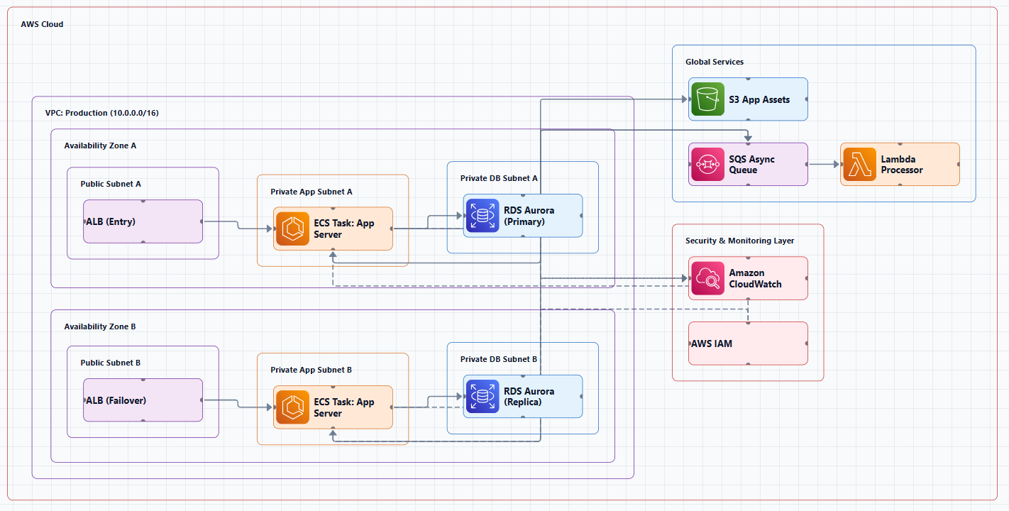
Think of it as the blueprint for your cloud network. A VPC architecture diagram answers critical questions:
AWS defines a VPC as a logically isolated virtual network in the AWS Cloud. You can configure your VPC by selecting IP address ranges, creating subnets, and configuring route tables, network gateways, and security settings.
The diagram typically shows the VPC as a container, with Availability Zones as sub-containers, and subnets, gateways, and resources placed within them.
Key Components of a VPC Architecture Diagram
Before diving into patterns, it's essential to understand the building blocks you'll see in every VPC architecture diagram.
1. VPC (Virtual Private Cloud)
The top-level container for your network. You define it with an IPv4 CIDR block (e.g., 10.0.0.0/16) and optionally an IPv6 CIDR block. VPCs operate within a single AWS Region and can span multiple Availability Zones.
In a diagram: A large rectangular container labeled with the VPC name and CIDR. Often drawn with a dotted or solid border.
2. Availability Zones (AZs)
Physically separate data centers within a Region. Deploying across multiple AZs is the foundation of high availability.
In a diagram: Sub-containers within the VPC, typically labeled "AZ-1," "AZ-2," etc. Each AZ contains its own subnets.
3. Subnets
Segments of your VPC's IP address range. Each subnet resides in a single Availability Zone.
- Public subnet: Has a route to an Internet Gateway. Resources here receive public IP addresses and can be accessed from the internet.
- Private subnet: No direct route to the Internet Gateway. Resources here are isolated from the internet.
- Database subnet: A dedicated private subnet for database resources, often with additional security controls.
In a diagram: Smaller boxes inside each AZ, labeled with their CIDR block and type (e.g., "Public Subnet 10.0.1.0/24").
4. Internet Gateway (IGW)
A horizontally scaled, redundant VPC component that allows communication between your VPC and the internet.
In a diagram: An icon at the VPC boundary, with an arrow pointing outward to the internet.
5. NAT Gateway
Allows instances in private subnets to initiate outbound traffic to the internet (e.g., for software updates) while preventing the internet from initiating connections to those instances. For high availability, deploy one NAT Gateway per Availability Zone.
In a diagram: Placed in the public subnet of each AZ, with arrows showing traffic flowing from private subnets through the NAT Gateway to the internet.
6. Route Tables
Contain rules (routes) that determine where network traffic is directed. Each subnet is associated with a route table.
- Public route table: Contains local routes plus a route to the Internet Gateway (
0.0.0.0/0 → igw-id). - Private route table: Contains local routes plus a route to the NAT Gateway (
0.0.0.0/0 → nat-gateway-id).
In a diagram: Often shown as a table icon or a small box near the subnet it controls, with arrows indicating where traffic is directed.
7. Security Groups (SGs)
Stateful virtual firewalls that operate at the instance/ENI level. They control inbound and outbound traffic to resources. Security Groups only contain ALLOW rules and are stateful, response traffic is automatically allowed.
In a diagram: Often shown as an overlay or badge on EC2 instances, or as a separate icon connected to the resources they protect.
8. Network ACLs (NACLs)
Stateless firewalls that operate at the subnet level. NACLs can contain both ALLOW and DENY rules and are evaluated in order. They apply to every resource in the subnet.
In a diagram: Often shown as a shield icon at the subnet boundary, or as a separate table associated with the subnet.
9. VPC Endpoints
Allow private connectivity to AWS services without traversing the internet.
- Gateway endpoints: For S3 and DynamoDB (free, regional).
- Interface endpoints (AWS PrivateLink): For other AWS services (ECR, Secrets Manager, etc.).
In a diagram: Icons placed inside the VPC, connected to the service they access.
10. VPC Flow Logs
Capture information about IP traffic going to and from network interfaces in your VPC. Enable flow logs on your VPC for comprehensive visibility.
In a diagram: An icon or annotation indicating that flow logs are enabled, often pointing to CloudWatch or S3.
Typical VPC Architecture Patterns
Here are the most common VPC architecture patterns, each with a diagram structure you can adapt.
Pattern 1: Single VPC with Public and Private Subnets (Two-Tier)
This is the foundational pattern for most AWS deployments. It separates resources that need internet access from those that don't.
Layout (nested groups):
[AWS Cloud]
  [Region]
    [VPC 10.0.0.0/16]
      [Internet Gateway]
      [AZ-1]
        [Public Subnet 10.0.1.0/24]
          - NAT Gateway
          - ALB
        [Private Subnet 10.0.2.0/24]
          - EC2 / ECS instances
          - RDS (primary)
      [AZ-2]
        [Public Subnet 10.0.3.0/24]
          - NAT Gateway
        [Private Subnet 10.0.4.0/24]
          - EC2 / ECS instances
          - RDS (standby)
Traffic flow: Users → Internet Gateway → ALB (public subnet) → EC2 instances (private subnet) → RDS.
Key design decisions:
- Public subnets host the load balancer and NAT Gateways.
- Private subnets host application servers and databases.
- NAT Gateways enable outbound internet access from private subnets.
When to use: Most production web applications, APIs, and microservices.
Pattern 2: Three-Tier VPC Architecture
Extends the two-tier pattern by separating application servers from web servers, with an internal load balancer between them.
Layout (left to right):
[Users] → [Internet Gateway] → [ALB (public subnet)]
  → [Web Servers (public subnet)]
  → [Internal ALB]
  → [App Servers (private subnet)]
  → [Database (private subnet, Multi-AZ)]
Why this works: Each tier has different security requirements and scaling needs. The presentation layer handles user requests, the application layer processes business logic, and the data layer stores sensitive information.
In a diagram: Three nested layers from top to bottom or left to right:
- Web Tier (Public): ALB + EC2/ECS instances in public subnets
- App Tier (Private): Internal ALB + EC2/ECS instances in private subnets
- Data Tier (Private): RDS Multi-AZ in private subnets
Network layers should be based on data sensitivity and access requirements. Components that require inbound internet access (public web endpoints) should be separated from those that only need internal access (databases).
When to use: Enterprise web applications with clear separation between frontend, business logic, and data.
Pattern 3: Production-Grade Multi-Tier VPC
A fully-featured production VPC with five distinct subnet tiers, as implemented by production-grade Terraform modules:
Subnet tiers:
- Public subnets: ALB, NAT Gateways (Multi-AZ)
- Private subnets: EKS/ECS workloads
- Database subnets: RDS/Aurora
- Intra subnets: No internet access (internal services)
- ElastiCache subnets: Caching layer
Additional components:
- VPC Endpoints (S3 Gateway, DynamoDB Gateway, SSM/ECR Interface endpoints)
- VPN Gateway
- VPC Flow Logs to CloudWatch/S3 with KMS encryption
When to use: Enterprise workloads running EKS, ECS, RDS, ElastiCache, and serverless applications.
Pattern 4: Hub-and-Spoke with Transit Gateway
For organizations with multiple VPCs (development, staging, production, shared services), a hub-and-spoke topology using Transit Gateway is the recommended approach.
Layout:
[Transit Gateway (Hub)]
  ├── [Production VPC (Spoke)]
  ├── [Staging VPC (Spoke)]
  ├── [Development VPC (Spoke)]
  ├── [Shared Services VPC (Spoke)]
  └── [On-premises (VPN/Direct Connect)]
Why this works: Transit Gateway is a network transit hub that interconnects VPCs and on-premises networks. Unlike VPC peering, Transit Gateway enables transitive routing, all connected VPCs can communicate through a central hub.
Key design decisions:
- Centralized egress VPC using a NAT Gateway
- Segregated environments for shared services, production, staging, and development
- Separate route tables per environment to isolate production
When to use: Organizations with multiple VPCs and environments requiring centralized networking.
Security Best Practices for VPC Architecture
1. Create Network Layers
Segment your network topology into different layers based on logical groupings of workload components according to their data sensitivity and access requirements.
Implementation guidance: In a three-tier web application, store static files on S3 and serve them from CloudFront, deploy the application layer with public endpoints on an ALB in public subnets, and deploy backend services and databases in private subnets.
2. Use Multiple Subnet Types
Separate entry, app, and data traffic:
- Public subnets: ALB, NAT Gateways
- Private application subnets: EC2/ECS workloads
- Private data subnets: Databases
One route table per tier.
3. Layer Security Controls
Use a defense-in-depth approach:
- Security Groups: Stateful, instance-level controls for fine-grained rules
- Network ACLs: Stateless, subnet-level controls for coarse controls
- VPC Flow Logs: Network observability and troubleshooting
Best practice: Use NACLs for broader, subnet-level traffic control (like blocking entire IP ranges) and Security Groups for fine-grained, instance-specific security.
4. Use NAT Gateways per Availability Zone
Remove single points of failure. NAT Gateways per AZ keep paths short and predictable and avoid cross-AZ data transfer costs. In a multi-AZ VPC, missing NAT Gateways in one AZ can force traffic across zones and raise transfer costs.
5. Use VPC Endpoints for Private Access
Keep traffic private and reduce exposure:
- Gateway endpoints: For S3 and DynamoDB
- Interface endpoints: For ECR, Secrets Manager, and other services
- Centralize endpoint management to reduce costs
6. Enable VPC Flow Logs
Enable flow logs on your VPC to automatically capture traffic. Start with a limited scope when first implementing flow logs, enable logging on a single subnet to understand data volumes and costs before scaling up.
7. Plan IP Addressing Carefully
- Use private IP address ranges following RFC 1918 guidelines
- Allow IP address space for more than one VPC per Region
- Within a VPC, allow space for multiple subnets across multiple Availability Zones
- Plan for IPv6 rather than retrofit it later
8. Use Infrastructure as Code
Make changes reviewable and reproducible. VPCs, subnets, and DNS should be written as Infrastructure as Code with required code review and CI checks for merges.
Common Anti-Patterns to Avoid
Creating all resources in a single VPC or subnet. This violates the principle of network layers and increases the blast radius of security incidents.
Constructing network layers without consideration of data sensitivity. Resources with different sensitivity levels should reside in different network layers.
Using VPCs and subnets as defaults for all network layer considerations. Consider how AWS managed services influence your topology.
Default VPC usage. The default VPC is not secure, with multiple IP addresses open to the public. Always create a custom VPC for production workloads.
No NAT Gateways per AZ. This forces cross-AZ traffic and incurs unnecessary costs.
Tools for Creating VPC Architecture Diagrams
You can create professional VPC architecture diagrams using:
Manual Tools
- Draw.io (diagrams.net): Free, browser-based, includes AWS icon libraries
- Lucidchart: Collaborative diagramming with AWS templates
- Microsoft Visio: Enterprise-grade diagramming
AI-Powered Tools
AI Line Studio generates AWS architecture diagrams from natural language descriptions in 15 to 20 seconds. For AWS-specific workflows, the dedicated AI cloud diagram generator turns descriptions into production-ready visuals. The AI architecture diagram builder helps build and refine VPC diagrams into production-ready designs.
Infrastructure as Code
Tools like Terraform and AWS CloudFormation can generate diagrams from your infrastructure code. Production-grade modules implement AWS Well-Architected Framework networking best practices including defense-in-depth subnet isolation, encrypted flow logging, and high-availability NAT Gateway deployment.
Ready-to-Use Templates
The AWS Labs aws-architecture-diagram skill provides ready-to-use patterns for common VPC architectures, including the VPC with Public/Private Subnets pattern.
Summary
An AWS VPC architecture diagram is the blueprint for your cloud network. A well-architected VPC prevents security issues, reduces costs, and makes troubleshooting infinitely easier.
Key takeaways:
- VPCs are region-scoped and span multiple Availability Zones
- Public subnets host load balancers and NAT Gateways; private subnets host application and database tiers
- Multiple subnet tiers (public, private application, private data, intra, cache) enable true network segmentation
- Security Groups provide stateful instance-level controls; NACLs provide stateless subnet-level controls
- NAT Gateways per AZ keep paths short and avoid cross-AZ data transfer costs
- VPC Endpoints keep traffic private and reduce internet exposure
- VPC Flow Logs provide network observability for troubleshooting and auditing
- Infrastructure as Code makes VPC changes reviewable and reproducible
The AWS Well-Architected Framework recommends segmenting your network topology into different layers based on logical groupings and data sensitivity. Benefits include restricting unnecessary pathways through the network and reducing the scope of analysis for inspection systems.
To start creating your own VPC architecture diagrams, explore the VPC AWS architecture diagram tool for templates and practical examples. For automated diagram generation, the AI cloud diagram generator turns descriptions into visuals instantly. For end-to-end system architecture beyond VPC networking, the AI system architecture generator covers distributed and enterprise system designs.