
Add Custom Node to AWS Diagram in AI Line Studio
You can add custom node to AWS diagram layouts in AI Line Studio by clicking the Add Node button in the header, typing a label, drawing a shape on the canvas, and dragging a connector to link it to existing components. This tutorial walks through the process using an already generated AWS three-tier web application architecture. After registering on the platform, you land on the Workspace page, select Cloud Architecture, and choose AWS to reach your diagram canvas.

YouTube Tutorial
Add Custom Nodes to AWS Architecture Diagrams AI Line Studio Tutorial 16
How to Add Custom Node to AWS Diagram in AI Line Studio
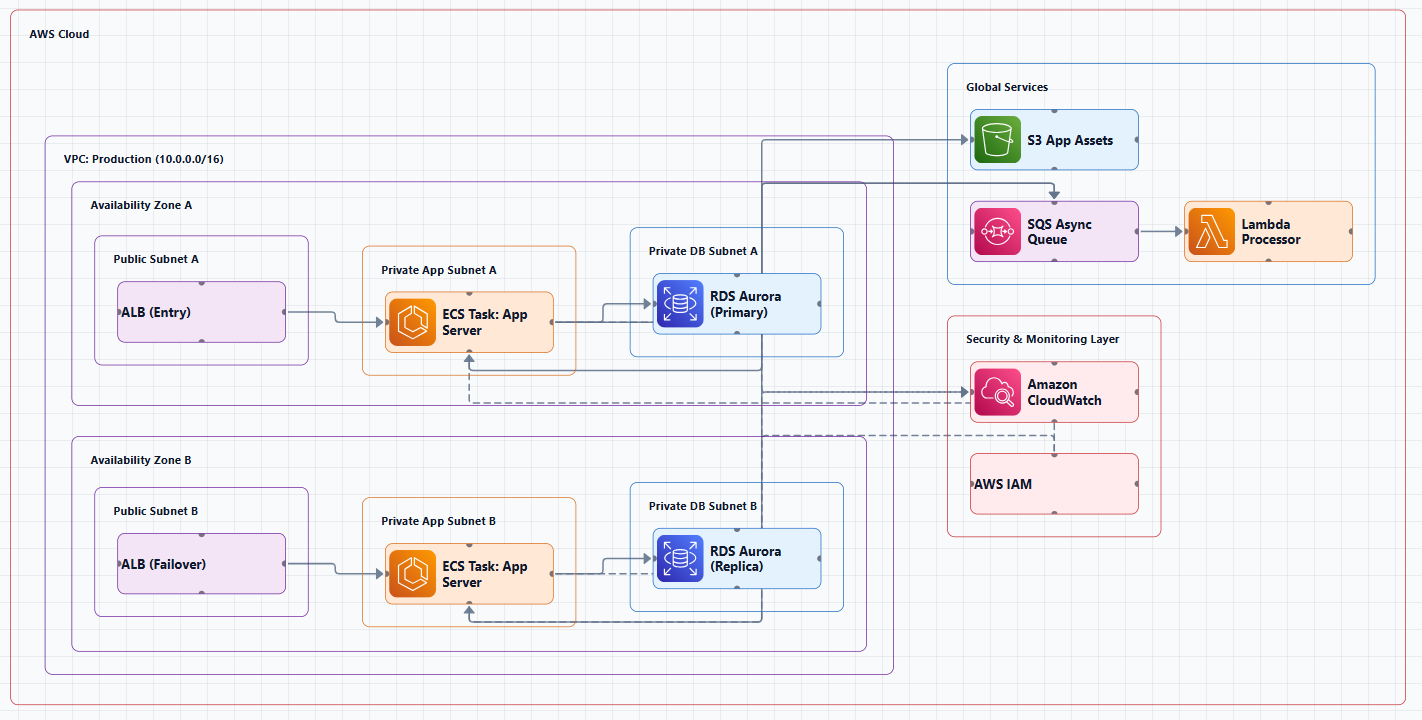
The ability to extend an AI-generated architecture with your own components is what turns a draft into a working document. When AI Line Studio generates an AWS three-tier web application diagram, it produces a solid foundation of official service icons and connections. But real infrastructure rarely fits a template exactly. You might need to represent a third-party integration, an on-premises gateway, a custom microservice, or a logical grouping that the initial generation did not capture. Custom nodes solve that problem.
Accessing Your AWS Architecture Canvas
The workflow starts immediately after registration. Once you log in, the platform redirects you to the Workspace page. From there, select Cloud Architecture and choose AWS as your provider. The tutorial assumes you already have a generated diagram on the canvas, specifically, an AWS three-tier web application architecture. If you are starting from scratch, generate that base diagram first, then proceed to add custom nodes on top of it.
For teams managing complex cloud estates, the cloud architecture diagram generator handles the initial layout automatically. That saves the time you would otherwise spend placing VPCs, subnets, EC2 instances, and RDS databases by hand. Custom nodes then let you layer in the specifics that make the diagram accurate for your actual environment.
Creating a Custom Node From the Header
To create a new node, look at the top header of the canvas interface and locate the Add Node button. Click it, and an input prompt appears. Type in the text you want to display on the node. The tutorial uses "AWS Service" as an example, but you can enter any label that describes your component, "Legacy API Gateway," "On-Prem DC," "Partner SFTP," or whatever fits your architecture.
After entering the text and clicking OK, move your cursor onto the canvas. Drag to draw a square or rectangle shape anywhere you want the node to appear. The node is created instantly at the size and position you define. There is no predefined shape library to browse and no forced styling. The rectangle is a blank container that carries your custom label.
This direct drawing approach is faster than hunting through icon libraries for a generic box shape. It also means you are not constrained by the official AWS icon set. If your diagram needs to represent something that does not have a standard service icon, a business process, a manual step, a future placeholder, you can mark it clearly without breaking the visual consistency of the layout.
Positioning Nodes on the Canvas
Once the custom node exists, it behaves like any other element on the canvas. Click and drag it to reposition it anywhere on the design surface. You can place it inside a subnet grouping, align it with a load balancer tier, or set it apart to indicate an external dependency. The drag interaction is smooth and unconstrained, so you can refine the layout until the spatial relationships accurately reflect your infrastructure logic.
Positioning matters because architecture diagrams communicate through proximity and alignment. A custom node placed near the database tier suggests a data dependency. A node placed outside the VPC boundary suggests an external integration. A node floating between two existing services suggests a translation or middleware layer. The tool gives you full control over those visual cues.
Connecting Custom Nodes to Existing Architecture
A standalone node is only half useful. The real value comes from linking it to the rest of the diagram. To connect your custom node to an existing AWS service icon, click on the custom node. Its color changes to green, indicating it is selected and ready for connection. Then drag a connector line from the green node and link it directly to any of the existing nodes on the canvas.
That connection is bidirectional in meaning even if it is drawn as a single line. It tells the reader that data, traffic, or dependency flows between your custom component and the official AWS service. During a design review, that single line can answer questions about integration points, failure domains, and network paths without requiring additional documentation.
For system architects who need to maintain diagrams that reflect real-world complexity, this connection capability is essential. It closes the gap between what the AI generates automatically and what the actual system requires. The result is a single diagram that contains both the standard AWS topology and the custom extensions that make the architecture unique to your organization.
Why Custom Nodes Matter in AWS Diagrams
AWS architectures are rarely composed entirely of first-party services. Most production environments include hybrid elements, legacy systems, third-party SaaS integrations, and custom code running on EC2 or EKS. A diagram that shows only official AWS icons paints an incomplete picture. It might look clean, but it omits the components that actually make the system work.
Custom nodes solve that omission without forcing you to abandon the generated layout. You keep the speed and accuracy of the AI-generated foundation, correct VPC shapes, proper subnet boundaries, accurate RDS and ALB icons, and supplement it with the exceptions and extensions that define your specific implementation. That combination is difficult to achieve in traditional tools, where you either build everything from scratch or fight against rigid templates.
If you are evaluating how this flexibility compares to manual diagramming, the comparison of AI Line Studio vs Draw.io highlights an important distinction. Draw.io offers an enormous shape library and deep formatting control, but adding a custom node still requires navigating menus, selecting shapes, and styling them manually. In AI Line Studio, the Add Node button and direct canvas drawing collapse that workflow into a few seconds. The tradeoff is less granular formatting in exchange for significantly faster iteration.
Keeping Your AWS Diagrams Current
The speed of adding custom nodes also affects how often you update your diagrams. When the process takes seconds instead of minutes, there is less friction to keeping documentation aligned with infrastructure changes. A new API partner, a migrated database, or a temporary failover environment can be added to the diagram immediately rather than waiting for the next documentation sprint.
To get the most accurate initial layout before you start adding custom nodes, refer to the how to write prompts for diagrams. A well-structured architecture description produces a cleaner base diagram, which means fewer custom corrections and a more stable foundation for your additions. The input guide covers techniques for specifying regions, availability zones, and service relationships in ways that the generator can parse precisely.
You can explore pricing plans to find the right fit for your team. The platform includes access to the AWS Cloud Architecture generator and the custom node features, so you can test the full workflow, from base diagram generation to custom node placement and connection, on your own projects.
For more tutorials on AWS diagramming, custom nodes, and cloud architecture best practices, visit the resources hub.
Key Takeaways
- You can add custom node to AWS diagram layouts by clicking Add Node, typing a label, drawing a shape, and connecting it to existing components.
- After registering, access your AWS canvas from the Workspace page by selecting Cloud Architecture and choosing AWS.
- The tutorial uses an AWS three-tier web application architecture as the starting diagram.
- Clicking a custom node turns it green, allowing you to drag a connector to any existing node.
- Custom nodes can be repositioned anywhere on the canvas by clicking and dragging.
Ready to customize your AWS diagrams?
Register on AI Line Studio, generate your base architecture, and start adding custom nodes to match your real infrastructure. Explore pricing plans to get started.
Explore Pricing PlansFrequently Asked Questions
The custom node feature lets you add your own labeled shapes to an existing AWS architecture diagram. You click the Add Node button in the header, type a label, draw a square or rectangle on the canvas, and then position and connect it to other nodes.